![[Home]](/chips.gif) HalSchematicsUsingGschem
HalSchematicsUsingGschemI added thread components (base,servo user1,2,3,4) each with 32 priority outputs the component is dbl-clicked to edit its speed (u32) it has 32 numbered pins (prioritized) to connect to functions (do i need corresponding input pins for and gates et al?) to test the tool, i created a schematic of 'stepper_mm' from ...configs/stepper this was to compare the hand generated .hal to the automated .halmost file the schematics, files, netlists and codes are herethe library goes into /usr/share/gEDA/sym upload:halGEDA.tgz

the differences between the /config files show what needs to be done...
  a) naming conventions need to be constant thru HAL
      motionDOTservoDOTlast-period  versus   motionDASHcommandDASHhandler
      (the former shows inheritance the latter is a bastard :P
  b) containers must be respected and kept together as much as possible
      motmod contains motion and axis
  c) division must be used to avoid huge widgets
      parport functions occur once for all parports used,
      it'd be redundant to have the functions in each parport widget,
      so a separate parport-function widget should exist
      so:
       make a parport-funct widget ( only one instance necessary for 1 thru N parports)
       make a parport-pin widget ( one needed for every parport)
       keep params for funcs with the func widget,
            parport readall time-max belongs with functions
       keep params for pins with the pin widget
            parport invert & reset belong with pins
      there will still be an parport-in-pins and a parport-out-pins widgets.


  d)individual halfiles wont result from a single graphic schematic
      multiple schematics dont know about other schematics
      multiple pages of one schematic may be useful
      but nets spread across files would be problematic
       (net name in file 1, pins added in file 3&6)
      i suppose its just reading all the files in a directory and building lists

it may well be back to the drawing board
esp since its getting more complicated to draw than to just text edit

picture of component collection
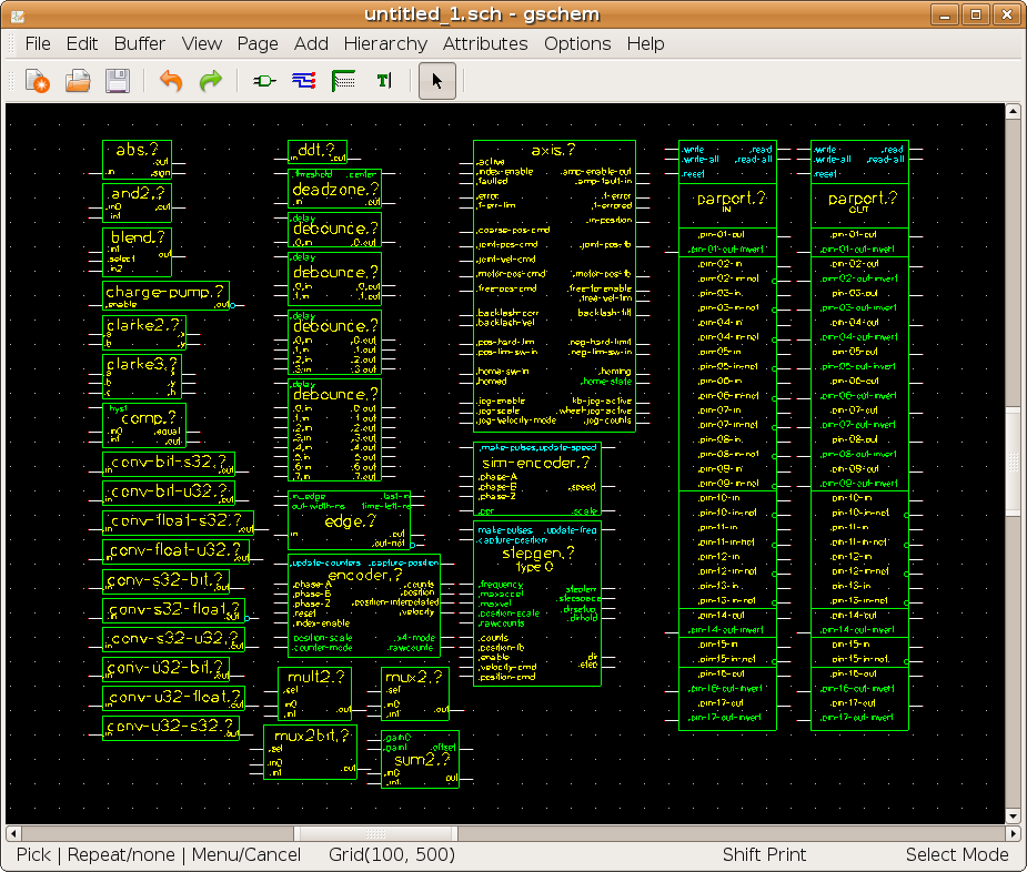
component bundle (is a directory named 'hal & belongs in /usr/share/gEDA/sym/ ) upload:hal2.tar.gz
python script upload:readGnetlist05.py
changes: uniform symbols, pins vs params vs funct are color coded, no more extra explanatory text
changes: files uploaded with old names to save space, dates in names are thus bogus
eg: and2 count=3the net lines are good (now as many pins as wanted on a net is ok )
eg: net mysig parport.0.pin-01-out mux2bit.3.out not.0.in mux2.0.sel
drc checks ok
syms check ok ( no more special attributes, 'author' is data type, 'comment' is pin/param/funct, 'description' is r,w,rw )
toolchain is:
  draw schematic using new hal component pallete
  connect pins as you like
  name the wires (thats the net name)
  save the schematic
  use gnetlist to make the netlist
   eg: gnetlist -g geda yourschema.sch -o yourschema.netlist
  process the netlist with a python script
   eg: python readGnetlist05.py newsyms-8jan2010.netlist >newsyms-8jan2010.halmost
  then handhack the threads etc ( its not all done yet )
example schematic
upload:newsyms-8jan2010.schpicture of example schematic

example output
   before process: upload:newsyms-8jan2010.netlist
   after  process: upload:newsyms-8jan2010.halmost
todo:
threads... connect components and functs to threads
These circuits have been described by text files.
with typical commands like the following...
When there are many connections, and devices, a more graphic tool is desirable.
I imagined a graphical layout tool with a pallete of hal components
and connections made by drawing lines between pins
and the ability to re-arrange and rubberband the components.
The electrical schematic toolset 'gEDA' may be suited for this use.
A library of hal components and drivers is being created to test the usefullness of this concept.
Users will be able to drag and drop components onto a canvas, and 'wire' the pins together.
At first it will just aid in visualization,
later it may save valid .hal files
Much later it may be used to enquire information from a running sytem,
or to be animated by live data.
Possibly these graphs can be automatically created from .hal files.
A tool set for schematic capture and pcb layout is being tested for this use.
This toolset is named gEDA, and it's circuit drawing tool is named 'gschem'.
gschem has a large pallet of devices already, but allows custom devices to be added.
These new devices appear as boxes with pins and text.
These devices can represent hal components and drivers.
gEDA can be had with 'sudo apt-get install geda'
a library of hal components is being built,
and the tarball can be accessed here
LIBRARY BAD AS OF 06NOV2009, WILL REPOST AFTER FIX
These files should be placed into a directory created by the gEDA install
'/usr/share/gEDA/sym/local/'