![[Home]](/chips.gif) CRC Cutter Radius Compensation
CRC Cutter Radius CompensationThere are two possible paths the cutter can take while cutter compensation is on to the left or right side of a line when facing the direction of cutter motion from behind the cutter.
To visualize this imagine you were standing on the part walking behind the tool as it progresses across the part.G41 is your left side of the line and G42 is the right side of the line.

 If the next move creates an outside corner the move will be to the end point of the compensated cut line.
 If the next move creates in an inside corner the move will stop short so to not gouge the part.
This is best to do on G-code using G41/G42 Example G41 D1 sets the Machine to Calculate the offset to the given G-code as tooltable Radius Left to the path direction!
You can get real quick good parts by doing a rough cut, a smooth cut, and a finish path with same tool, but with different diameter values.
Where G10 L1 P1 R2.49 is used to set the tooltable out of the G-code so no handling to the tooltable is needed
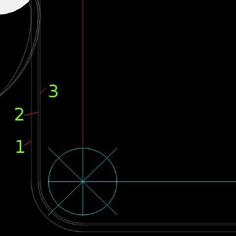
picture above shows the effect of a g-code program like
G17 G21 G54 G90 G61
(Working on G10 L1 setting tooltable at runtiume)
(T1 Real diameter 4.98 D1 G10 L1 P1 R2.49)
(T1 Rogph Diameter 6.0 D1)
(T1 Smooth diameter 5.2 D1)
T1 M06
G00 X-5 Y5 S100 M03
Z2
G01 Z-5 F100
G10 L1 P1 R3
G41 D1 (call first tool Diameter Rogph)
(Path simple square)
O100 sub
G03X0 Y10 I0 J5 F1200
G01 X0 Y20
X20 Y20
X20 Y0
X0 Y0
X0 Y10
G03X-5 Y15 I-5 J0
G00 Z30
(CRC off in sub)
G40
O100 endsub
(roghing path)
O100 call
(reset to the startpoint)
G00 X-5 Y5 S100 M03
Z2
G01 Z-5 F100
(change tooltable and reload tooltable with G10)
G10 L1 P1 R2.6
(call the smooth path)
G41 D1
O100 call
(finish path)
G00 X-5 Y5 S100 M03
Z2
G01 Z-5 F100
G10 L1 P1 R2.49
G41 D1
O100 call
M30
This is best to use if you will often change parts.
you can also set more tool diameters in the tooltable and use the offsets Dxx
G41 D11 ...G41 D1
it is common use to set T1 T11 T21 as the same tool and use D1 D11 D12 as the Diameter CRC offset values.