![[Home]](/chips.gif) Lathe Advanced Features
Lathe Advanced Features
Note: These features are not yet implemented in EMC, and this page is mainly meant to be a discussion/wishlist of sorts, where after a consensus is reached the features can be added to EMC. For Lathe-specific features already implemented in EMC, check Lathe Code.
== # Feedrate as units/rev (Done)== A G-code (possibly G96) that would change the feedrate from the standard units/min to units/rev. This would be a good feature becuase typically all feedrates are programmed in mm/rev (so that rpm changes don't affect the surface & feedrate/turn). This feature coupled with CSS also gives a much more optimised time for making a part, and a longer lifespan for the cutting tool.
Typically this is the default unit for feedrate
Example code:
...
G96 F0.25 (Sets feedrate to units/rev, and specifies feedrate to 0.25 units/rev)
...
G94 F100 (Sets feedrate back to units/min, and sets feedrate to 100 units/min)
...
G96/G94 without the F parameter should give an error
Example code:
...
G92 S3000 (Sets the max rpm to 3000rpm)
G96 F0.25 (Sets feedrate to 0.25 units/rev)
G97 S200 (Sets speed to 200 CSS (typically meters/min))
...
G95 S1000 (Sets speed back to RPM, possibly for drilling. Feedrate still in units/rev)
...
G97 S100 (Sets speed back to CSS)
...
A G97 without the S parameter should give an error
NOTE: In some systems G97 also activates G96, making the code instead: G97 F0.25 S200 (CSS, *also* units/rev, and the parameters). I'm not sure of a situation where one would want G97 and G94, but it seems better to leave that up to the user than forcing G97 to entail G96.

Also, the G41/42 behavior is not the same as in a mill when choosing what is "left" and "right". The rule of thumb is to rotate the current working environment so that the material is down. Then the position of the tool compared to the billet determines whether it's right or left. (See image)

Typically you would activate compensation when doing a toolchange and choosing the tool (this would at the same time apply tool-length offsets)
example code (fanuc style):
...
T0101 (the first 01 selects the turret position, the second 01 selects the offset/radius/tool-orientaion values, where in position 1 in the register (maybe a text file or something) there would be:
X offset, Z offset, Radius, Cutter orientation
50,20,0.8,3 (standard tool)
0,100,0,7 (drill)
0,100,, (same effect as drill above)
T0103 is a valid (although practically rather unusual) command.
T01 is valid, but does not apply any compensation
Note: the formatting for the register was just made up in five seconds, and is not the same as the type in commercial lathes, as they have a GUI to change things like that.
Typically in commercial CNC lathes there is a register where one can input the maximum plunge angle for a tool, plunging more than allowed in the register gives a warning message. For example, this
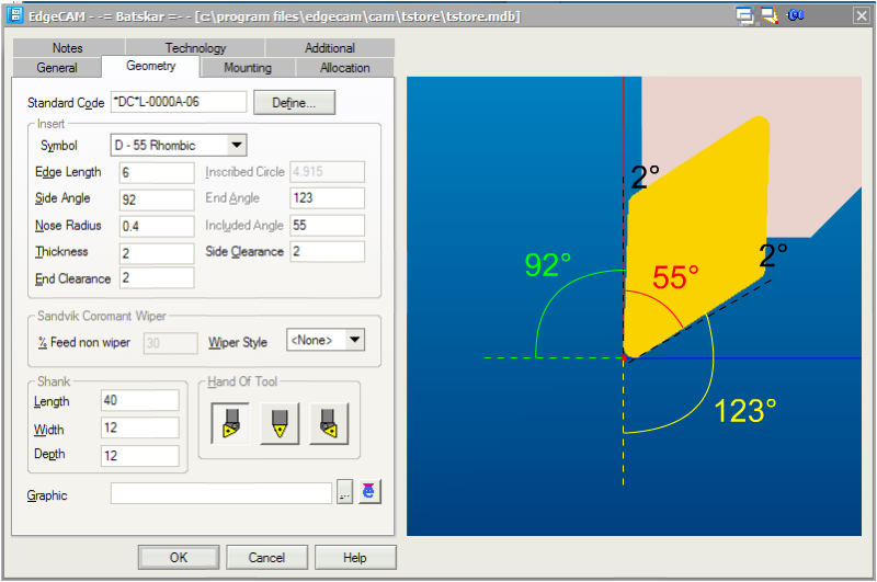
would have a maximum plunge angle (end angle in the image) of something like 31° (123° (angle to -Y axis)-90°(to get to +X axis)-2°(typically one has a margin of 2° in case of improper toolsetting and so that the back end doesn't lie against the material and possibly harden it). A roughing tool that is more square shaped typically has a lower value. Although most commercial lathes don't add support for an upper angle (side angle in the image), it may be good to have that too. In this case the upper angle would be 0° (the tool cannot cut concave parts, it can only cut straight up/down), becuase of the 2° margin.
This register is suitably the same register as the one for tool offset and nose radius.
Example code:
G92 S3000
G96 F0.25
G97 S200
G0 X20 Z1
GXX,Rough_turn <or> N70,N150,2 (material removed per pass), 0.1, 0.3, 0, 0.3, 0.1, 1 <rough only> OR 2 <finish only> OR 3 <rough then finish>
...
Either:
Rough_turn
G01 X20 z2 (start of finished profile)
...
...
...
M17(end of finished profile)
OR
N70 G01 X20 Z2 (start of finished profile)
...
...
...
N150 G01 X50 Z-30 (end of finished profile)
As it stands today we don't know of any sane canned cycle spec, so probably EMC will have it's own canned cycle (see: CannedCycleProposal), with these parameters:
Pitch - Specifies the pitch (distance between common points on a thread) of the thread.
TPI - Specifies the number of threads per inch.
Speed - Specifies the spindle speed of the turning centre in RPM. If you have previously selected Constant Surface Speed using the CSS (M-Functions) command, this spindle speed is measured in surface speed (metres or feet) per minute.
Link Type - Specifies which of the moves into or out of each cut are to be "chased" or feed moves:
Chase Both - This is the default setting, with both moves at the feed rate.
Chase In - The move into the cut is a feed move, the move out of the cut is at rapid.
Chase Out - The move into the cut is at rapid; the move out of the cut is a feed move.
No Chase - Both moves are made at the rapid rate.
Safe Approach - Check to use the Safe Approach strategy on the initial approach move. This causes approach moves to be split into two separate blocks. If a radially mounted tool is in use the approach will be in the order Z and then X. For an axially mounted tool the order will be X and then Z.
Approach Angle - Specifies the compensation angle for the start position of each pass, measured clockwise from the tool cut direction.
Retract Angle - Specifies the retraction angle for the end of each threading pass, measured anticlockwise from the tool retract direction.
Lead In - Specifies the tool lead in distance as the number of Pitch lengths the tool must lead in by along the line selected as the drive line for the cycle.
Lead Out - Specifies the tool lead out distance as the number of Pitch lengths the tool must travel beyond the end of the selected drive line.
Finish At - Select the finish point for the cycle to be at the Cycle Start or Cycle End.
Degression Factor - Specifies a factor to calculate how the depth of cut for each successive pass is reduced.
Degression Factor
= 1;produces a constant depth cut.
= 2;produces a constant volume cut (the default).
Specifying intermediate factors produces results between these two states.
The depth of cut for the current pass is calculated using this equation:
Depth = Cut Increment * (Pass^(1/Degression?))
where:
Depth
The depth of cut for the current pass.
Cut Increment
The specified Cut Increment parameter.
Pass
The current pass number.
Degression
The specified Degression Factor parameter.
Total Depth - Specifies the total depth of the thread as measured from the crest of the thread to the root.
Cut Increment - Specifies the distance the tool moves in the cut direction with each pass. If the cut factor is not 1.0 then the Cut Increment represents only the first depth of cut as the toolpath will degress in depth.
Number of Passes - Specifies the total number of cutting passes for the tool to reach the Total Depth (less any Spring Depth).
Final Increment - Specifies the last cut increment. Actual cut increments for each pass are interpolated from the Cut Increment and the Final Increment.
Start Depth - Specifies an offset start depth from the drive line.
Spring Cuts - Specifies the number of finishing passes made from the Spring Depth to the Total Depth. This allows for any "spring" in the tool.
Spring Depth - Specifies the depth of material to be removed using spring cuts (typically 0, the "springback" of the material gives for a small depth).
"The Graphics mode is the safest way to check a programmed tool path. You could also try using the handle feed override while in Memory mode; this is useful when setting up a job where the tool comes close to the chuck (within a couple thou’). Single-block through the program and override the feed to a stop if you want, then check your “distance to go” on the Current Commands page. You can feed hold and stop the spindle to make sure the distance to go doesn’t exceed the gap between the tool and the chuck jaws. This method is better than using Dry Run, because you can slow the feed down to 1% (or 0%) and react quicker if it looks like the tool will cut into the face of the jaws. To review:
"1) Run the program in Graphics to check the tool path.
"2) Run the program in Memory, with rapid override at 5%, and use the jog handle for feedrate override. Use the “distance to go” display on the Current Commands page to compare tool position relative to the workpiece (the spindle may be stopped at any time to check the gap).
"3) This is also a good time to make sure other tools and index points clear the workpiece, chuck and tailstock.
"Another alternative is to turn on Setting 103, so that the Cycle Start and Feed Hold functions are both controlled by the CYCLE START button. Hold the button in and the program runs; release it and the machine stops in a feed hold. This is a very useful setting, but remember to turn it off when you’re through using it.
Sincerely, Haas Applications