![[Home]](/chips.gif) History of VFD Digital/Analog Interface
History of VFD Digital/Analog Interface|
Connecting EMC2 to a VFD digital/analog interface begins with consulting the VFD manual to find what digital and analog features are available and what forms of signals are acceptable. Many of the manuals are available as downloads from the manufacturer's website, even for very old drives. |
|
Connecting EMC2 to a VFD digital/analog interface begins with consulting the VFD manual to find what digital and analog features are available and what forms of signals are acceptable. Many of the manuals are available as downloads from the manufacturer's website, even for very old drives. One of the simplest ways for EMC2 to provide an analog like signal is with a PWM or PDM signal. The following schematic is an example of using a PWM channel from a Pluto-P to feed the 0-10 V analog input to a VFD on my mill. 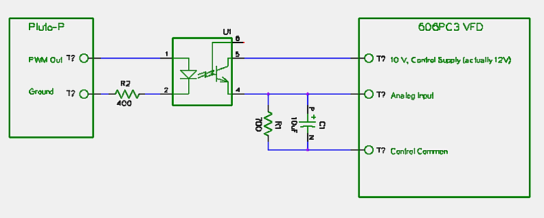 U1 could be just about any common opto-isolator. I happened to use a 4N35. U1 switches the control supply voltage into the capacitor C1. At a low PWM duty, C1 gets filled with a small charge or voltage. At 100% duty, 10 Volts is supplied constantly to C1. While the PWM signal is off, the charge drains through the resistor R1, otherwise C1 would tend to hold full charge even with short duty cycles. In my case I adjusted R1 until I got 10 Volts on the input with close to 100% duty. EMC2 has a pwmgen component that could be tied to a parallel port output pin to provide the same PWM signal as the Pluto or other hardware signal generator, except with a much lower PWM frequency and less resolution. I tried pwmgen first, which worked okay, but I had the Pluto-P on hand and it works better. Ideally, the analog input voltage would be stable, but also follow the desired speed command as closely as possible. A PWM signal being ether 0 or 10 Volts is very unstable. C1 is used to smooth the PWM. If a larger C1 is used, or a smaller R1, the charge will drain more slowly, making the voltage more stable, but also react to a commanded voltage change more slowly. A higher PWM frequency will allow C1 to be smaller for the same voltage drain, and also allows for a faster reaction time. Usually, for a spindle control setup, reaction time is not a big issue, but a balance of C1, R1, and PWM frequency will need to be addressed. The value of R2 is adjusted to limit the current going through the opto-isolator. The Pluto-P is a 3 Volt device, so 400 Ohms is about right for a 10 mA current limit. A 5 Volt or higher signal should use a higher value resistor. |