Using the Mesa Electronics M5I20 board to control a CNC laser using EMC software. The CNC device is a [G100 Laser] which has a DB-25 connector that allows the user to change power settings and monitor the condition of the system based on six output signals. A custom circuit board was designed to interface between the laser and the M5I20 board. The custom PCB provides the status of the laser to M5I20 board and also receives data from the M5I20 to generate pulse width modulation (PWM) signals for the laser. Yes, I'm aware that its possible to get EMC to generate PWM signals, but I wanted to have an independent system generating PWM because it simplifies testing and running of the system.
A block diagram of the system is shown here.
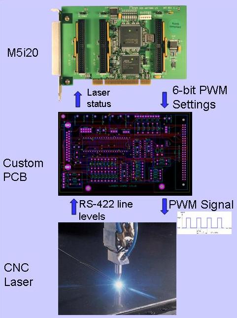
The custom circuit board is composed of a [DB-25 connector which connects to line driver circuitry], and an [anchorM5i20 IDC connector] which connects to an on board [anchorAVR AT90s8515 microprocessor]. The board was designed to monitor conditions of various pins to throw a firmware exception when the laser was failing; and it grabs bits from the M5i20 to generate PWM signals. The microprocessor [firmware] may be a bit confusing in that it converts the 6 bits of data to the the acceptable working range of pulse-widths for the laser, which is 5% to 60% duty cycle. Other than that its pretty straightforward. The circuitry was generated in [Labcenter's Proteus], and a [PCB] was generated by [Pool]. Almost all parts were ordered from[Mouser]. I like their selection and records tracking better than other vendors.
Installing the M5i20. This was a little unfriendly. In part it required some digging on the [wiki] for debugging using [lspci], that was fine, but ultimately I discovered my bios simply didnt like having a lot of PCI cards loaded onto the motherboard. The first incarnation of the custom PCB actually plugged into a PCI slot and connected to two pins: ground and +5v. Even that was enough to get the computer to register I was using a slot and it would have addressing problems! So eventually I cut the tabs from the custom PCB to the PCI and derived power from the M5i20 over the IDC cable. That cured the mother board addressing issues. To get to the "hey honey I got my computer to talk to this expensive card" moment, I used the [Halvcp Test Panel] created by Anders Wallin and an oscilloscope connected to M5I20 pins.
Running the M5i20 from hal.
To simplify my thinking about connecting to the M5i20 I made a
[pinconnections.htm table] describing the links between the ports on
the AT90s8515 chip, the DB-25 connector of the laser and the 50 pin
IDC connector of the M5i20. This was very useful when I got into
linking the pins of the EMC M5i20 halpins to the rest of the
system. As usual, the EMC team has put together really
[extensive
documentation]. Armed with
[the driver for the
M5i20] I was able to code up just about everything without bugging the
\#emc-devel folks. Basic tricks for debugging the hal involve starting
up emc with my current .ini file, and running:
halcmd show pin
and...halcmd show sig
Frequently I would perform
halcmd newsig test_sig1 bit
and...halcmd linksp test_sig1 pin
... but I'm not much more advanced than that.
My .hal file contains set of calls:
newsig PWM1-bit bit
newsig PWM2-bit bit
newsig PWM4-bit bit
newsig PWM8-bit bit
newsig PWM16-bit bit
newsig PWM32-bit bit
among other which will be signals that are linked to the interface.
Driving the hal from pyvcp. As the [documentation] for Virtual Control Panels shows, a nice interface can be built using widgets like buttons, LEDs and meters which can be laid out in a vcp.xml file. In this case LEDs were used to display the status of the laser, a button fires the laser manually, and a meter displays the power settings of the laser.
For example, this .xml code was used to make a meter.
<halpin>"power-meter"</halpin>
  <text>"Power"</text>
  <size >200</size>
  <min_>0</min_>
  <max_>100</max_>
</meter>
And calls like this will set the halpin "power-meter" to 5 in my .hal file.
setp pyvcp.power-meter 5
Some signals were created above that correspond to PWM bits, calls like this will link each signal to the M5i20 board, and an LED in the vcp:
net PWM1-bit => m5i20.0.out-08 pyvcp.led-21
Example of vcp.hal file
upload:laser_vcp.hal
Example of vcp.xml file
upload:laser_vcp.xml
As the documentation notes its possible to load your vcp.xml specification into axis directly, by putting the line:
PYVCP = laser_vcp.xml
into the [DISPLAY] section of the .ini file.
Then also place:
POSTGUI_HALFILE = laser_vcp.hal
in the [HAL] section of the .ini file.
A screen shot of the vcp... [is here]
EMC provisions for a very interesting system that allows calls to executables to made directly from G-code. This created a straightfoward mechanism to set the power of my laser during machining. Commands can be named from M100 to M199, and the Mnnn programs must be stored in the directory described by PROGRAM_PREFIX in the [DISPLAY] section of the .ini file. In my case, I created a perl executable program with the following listing:
#!/usr/bin/perl
use strict;
my $input = $ARGV[0];

$input =~ s/P//;

$input = 0 if ($input < 0);
$input = 99 if ($input > 99);

my $cmd = "halcmd setp pyvcp.power-meter $input";

system $cmd;

my $val = int($input * (64 / 100));

my $bit;

foreach $bit (1, 2, 4, 8, 16, 32) {

    my $pwm = $val & $bit;

    my $n = 0;
    $n = 1 if ($pwm != 0);

    $cmd = "halcmd sets PWM" . $bit . "-bit $n";
    system $cmd;
}
The arguement passed to the program specifies the power setting which ranges from 1-99. The program normalizes this value to 64, and performs bitwise AND operations on the value. Non-zero values resulting from the bitwise AND are sent out as bit signals of 1, zero values of the bitwise AND result in zeros being sent.
Hopefully you can tell from the code in the perl program how it makes the call:
halcmd sets PWM1-bit 1, etc...
which set the signals of the hal to the appropriate value. The M5i20 bits are picked up by my custom circuit board, and those signals are converted to PWM values.
When EMC launches the gcode parameters are passed to the Mnnn
command using P and Q values as arguments at runtime. Thus, the
call:
M102 P50
passes the string "50" to the perl program as the $ARGV[0] variable. This value is used to set power meter in the vcp to 50%, and the appropriate bit settings are sent to the laser.
[EMC2 documentation]
[Halvcp Test Panel]
[Mesanet's M5i20 Page]
[Coherent G100 Laser]
[My laser site.]
![[Home]](/chips.gif)
![[DB-25 connector which connects to line driver circuitry]](http://wiki.linuxcnc.org/uploads/card_p1.JPG)
![[anchorM5i20 IDC connector]](http://wiki.linuxcnc.org/uploads/card_p2.JPG)
![[anchorAVR AT90s8515 microprocessor]](http://wiki.linuxcnc.org/uploads/card_p3.JPG)
![[PCB]](http://wiki.linuxcnc.org/uploads/card_pcb.JPG)
![[is here]](http://wiki.linuxcnc.org/uploads/Screenshot.png)