Lathe support on non-emc2 controls<html><h1> This page does NOT describe how emc2 works. Instead, it describes how other controls work. In some cases, emc2 may work similarly to the descriptions below. In other cases, it will work entirely differently.</h1></html> |
Lathe support on other controls<html><h1> This page does NOT describe how LinuxCNC works. Instead, it describes how other controls work. In some cases, LinuxCNC may work similarly to the descriptions below. In other cases, it will work entirely differently.</h1></html> |
1.1. This is fanuc style canned cycle |
1.2. This is a Fanuc style canned cycle |
|
2) Tools->Read: Read in an odthreading tool Tools->Read Tool ( this is a loop so after you read the first one you have to CANCEL twice to stop reading ) |
|
2) Tools->Read: Read in an OD threading tool Tools->Read Tool ( this is a loop so after you read the first one you have to CANCEL twice to stop reading ) |
G32 is used for Plain Threading Cycle
G33 Threadcutting, constant lead
G34 Threadcutting, increasing lead
G35 Threadcutting, decreasing lead
G46 is used for Turning Canned Cycle
G47 is used for Facing Canned Cycle
G66 is used for Stock Removal Roughing
G67 is used for Stock Removal Finishing
G76 is used for Canned Cycle, Thread Cutting Cycle
G70 is used for Canned Cycle, Finishing Cycle
G71 is used for Canned Cycle, OD Roughing Cycle
G72 is used for Canned Cycle, Face Roughing Cycle
G73 is used for Canned Cycle, Profiling Cycle
G74 is used for Canned Cycle, Face Grooving Cycle
G75 is used for Canned Cycle, OD Grooving Cycle
G90 is used for Cutting Cycle A
G92 is used for Thread Cutting Cycle
G94 is used for Cutting Cycle B
M10 Clamp
M11 Unclamp
M12 Synchronization Code
M19 Oriented Spindle Stop
M00 PROGRAM STOP (SETTING 42, 101)
M01 OPTIONAL PROGRAM STOP (SETTING 17)
M02 PROGRAM END
M03 SPINDLE ON FORWARD (S) (SETTING 144)
M04 SPINDLE ON REVERSE (S) (SETTING 144)
M05 SPINDLE STOP
M08 COOLANT ON (SETTING 32)
M09 COOLANT OFF
M10 CHUCK CLAMP (SETTING 92)
M11 CHUCK UNCLAMP (SETTING 92)
M12** AUTO AIR JET ON (P)
M13** AUTO AIR JET OFF
M14** MAIN SPINDLE CLAMP
M15** MAIN SPINDLE UNCLAMP
M17 ROTATE TURRET FORWARD (T) (SETTING 97)
M18 ROTATE TURRET REVERSE (T) (SETTING 97)
M19** ORIENT SPINDLE (P,R)
M21** TAILSTOCK ADVANCE (SETTING 93, 94, 106, 107, 121, 145)
M22** TAILSTOCK RETRACT (SETTING 105)
M23 ANGLE OUT OF THREAD ON (SETTING 95, 96)
M24 ANGLE OUT OF THREAD OFF
M30 PROGRAM END AND RESET (SETTING 2, 39, 56, 83)
M31 CHIP AUGER FORWARD (SETTING 114, 115)
M32 CHIP AUGER REVERSE (SETTING 114, 115)
M33 CHIP AUGER STOP
M36** PARTS CATCHER ON
M37** PARTS CATCHER OFF
M41 SPINDLE LOW GEAR OVERRIDE
M42 SPINDLE HIGH GEAR OVERRIDE
M43 TURRET UNLOCK (FOR SERVICE USE ONLY)
M44 TURRET LOCK (FOR SERVICE USE ONLY)
M51-M58 OPTIONAL USER M CODE SET
M59 OUTPUT RELAY SET (N)
M61-M68 OPTIONAL USER M CODE CLEAR
M69 OUTPUT RELAY CLEAR (N)
M76 PROGRAM DISPLAYS INACTIVE
M77 PROGRAM DISPLAYS ACTIVE
M78 ALARM IF SKIP SIGNAL FOUND
M79 ALARM IF SKIP SIGNAL NOT FOUND
M85** AUTOMATIC DOOR OPEN (SETTING 51, 131)
M86** AUTOMATIC DOOR CLOSE (SETTING 51, 131)
M88** HIGH PRESSURE COOLANT ON (SETTING 32)
M89** HIGH PRESSURE COOLANT OFF
M93** AXIS POSITION CAPTURE START (P,Q)
M94** AXIS POSITION CAPTURE STOP
M95 SLEEP MODE (hh:mm)
M96 JUMP IF NO SIGNAL (P,Q)
M97 LOCAL SUB-ROUTINE CALL (P,L)
M98 SUB-PROGRAM CALL (P,L)
M99 SUB-PROGRAM/ROUTINE RETURN OR LOOP (P) (SETTING 118)
M109** INTERACTIVE USER INPUT (P)
M110** TAILSTOCK CHUCK CLAMP (SETTING 122)
M111** TAILSTOCK CHUCK UNCLAMP (SETTING 122)
M119** SUB-SPINDLE ORIENT (P,R)
M121-M128 OPTIONAL USER M CODE INTERFACE WITH M-FIN SIGNAL
M133** LIVE TOOL DRIVE FORWARD (P)
M134** LIVE TOOL DRIVE REVERSE (P)
M135** LIVE TOOL DRIVE STOP
M143** SUB-SPINDLE FORWARD (P)
M144** SUB-SPINDLE REVERSE (P)
M145** SUB-SPINDLE STOP
M154** C AXIS ENGAGE (SETTING 102)
M155** C AXIS DISENGAGE
M164** ROTATE APL GRIPPERS TO "n" POSITION (Pn)
M165** OPEN APL GRIPPER 1 (RAW MATERIAL)
M166** CLOSE APL GRIPPER 1 (RAW MATERIAL)
M167** OPEN APL GRIPPER 2 (FINISHED MATERIAL)
M168** CLOSE APL GRIPPER 2 (FINISHED MATERIAL)
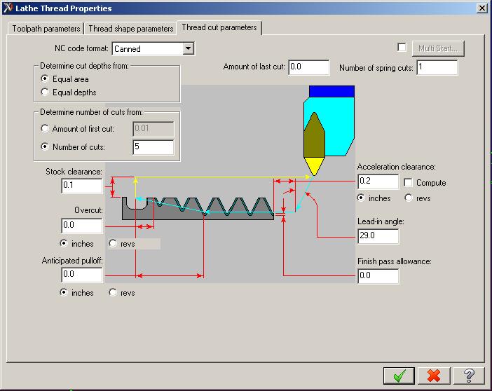
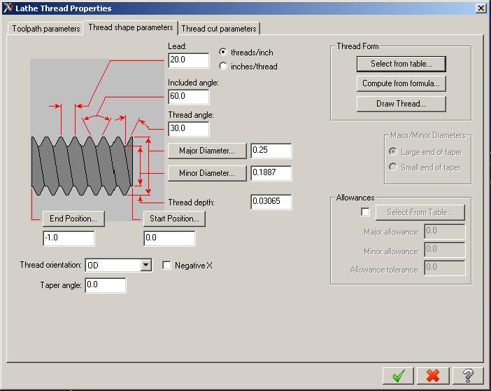
They select either tpi or lead using a parameter elsewhere.
m = Number of finishing cuts r = Chamfering amount a = Angle of tool tip d min = Minimum cutting depth (specified in radius value) d = Finishing allowance (in radius value)
X = X axis destination Z = Z axis destination i = Taper value (in radius value) k = Height of thread (in radius value) dd= Depth of first cut (in radius value) l = Lead of thread
Example: G76 P010060 Q100 R200; G76 X60.64 Z-25. P3680 Q1800 F6.;
Cuts a thread with one finishing cut, no chamfer on the exit of the tool, with a tool tip angle of 60deg. It will have a minimim depth of cut of .1mm and will have a finishing allowance of .2mm. The minor diameter of the thread is 60.64mm and it will cut a thread 25mm long in the Z minus direction. The height of the thread is 3.68mm and the depth of the first cut is 1.8mm and the thread has a lead of 6mm. This thread is a straight thread with no taper.
(q and a borrowed from cad_cam_edm_dro group about 2002)
Are Q, R, I, and the second P always in the implied decimal format? Since Z, X, and F are decimalized, it seems kind of strange to mix the two in the same code - doubly so since retrofits have all kinds of different resolutions.
Yes for some reason Q,R,I and the 2nd P are as I put in the example, I don't know why but as I said all three Fanuc machines that I have use the same format. Possibly this could be changes in the parameters of the machine.
I'm a bit unclear the effect of the chamfering amount in the second two chars of the P word. Is the thread chamfered with the threading tool explicitly by the G76 cycle? Seems like one would want to to this with another tool, but I guess it could be pretty convenient though as part of the threading action. Or is this just "stay out" information so the cycle can be optimized?
The chamfering amount is on the retraction of the tool at the end of the thread. If you leave this amount at 00 the thread will end in a groove (no chamfer) but if you use 05 this will chamfer the thread out to the major diameter of the thread for a distance of 5mm.
Gxxx LATHE THREAD CYCLE <OD/ID/TAPER/MULTIPLE-START/VARIABLE LEAD>
  Inch/Metric?
  Absolute G90 Mode Only
  With The Exception of M3/M4 No Other M or G Codes Allowed
  NOTE: CYCLE IS DEVELOPED FOR DIAMETER COMPENSATION, G41/G42 AND
        ENDS IN G40 MODE.
        CYCLE WILL POSITION Z AXIS (1) PITCH + .11 INCH, 2.76 MM
        BEFORE G33 IS ACTIVATED.
 Gxxx FORMAT:
 REQUIRED: Gxxx B..E..J..O..R..U..V..W..Z..
 OPTIONAL: N..Gxxx A..B..C..D..E..F..H..I..J..K..M..O..Q..R..S..U..V..
           W..X..Z..
    NOTE: Because of 80 character line limitation, it may be necessary to
          pass-in letter address values, in Two or More Lines. See below:
                                            ---
 FORMAT:
    N10 Gxxx A..B..C..D..E..F..H..I..J..K..  First line up to 80 characters
N20 M..O..Q..R..S..U..V..W..X..Z.. Second line up to 80 characters
    NOTE: CYCLE WILL NOT EXECUTE AXIS MOTION UNTIL Z VALUE IS PASSED-IN.
          ALWAYS PASS-IN Z VALUE IN LAST LINE.
LETTER ADDRESS ASSIGNMENTS:
 A = Infeed Angle. <10 Deg. Default>
 B = Number Of Rough Passes.
 C = Number Of Spring Passes. <0 Default>
 D = Variable Lead, Final Lead Value At End Of Thread. <Default E Value>
 E = Initial Lead Value At Beginning Of Thread. <Pitch>
 F = Positioning Feedrate. <Default Modal Rate>
 H = Number Of Thread Starts (1 Start Default)
 I = First Pass Incremental Depth. <Default Cycle Calculated Depth>
  NOTE:IF "I" IS PASSED IN, THEN ALL SUCCESSIVE ROUGH CUT DEPTHS WILL BE THE
      <TOTAL DEPTH-1ST DEPTH/NUMBER OF RGH. CUTS-1.=SUCCESSIVE DEPTHS>
       E.G. (.0625-.02/10.-2.)=.0047 FOR EACH SUCCESSIVE PASSES.
       IF "I" IS NOT PASSED IN, THEN ALL ROUGH CUT DEPTHS WILL BE CALCULATED
         BY CYCLE. <TOTAL DEPTH/SQUARE ROOT OF NUMBER OF CUTS=1ST DEPTH>
         <SQUARE ROOT OF LAST CUT+1. * 1ST DEPTH=SUCCESSIVE DEPTH>
       E.G. (.0625/SQRT(10.)=.0198) 1ST DEPTH
            SQRT(2)*.0198=.0280-.0198=.0080 2ND DEPTH
            SQRT(3)*.0198=.0343-.0280=.0063 3RD DEPTH, ETC.
 J = Finish Pass Incremental Depth.
 K = Plus Or Minus Taper Per Inch/Millimeter?. Plus Taper = +Z DIA. < -Z DIA.
     Example of Plus Taper    .75/ft = K,.75/12. or K.0625
     Example of Minus Taper  -.75/ft = K,-.75/12. or K-.0625
     <0 Taper Default>
     NOTE: CYCLE WILL CONVERT DIAMETER TAPER INTO RADIUS TAPER, <L811/2.>
 M = Spindle On, M3-CW/M4-CCW.
 O = Tool Orientation. 1, -1, 2, or -2.
     O =  1. OD Thread - Tool Tip +X Direction
     O = -1. ID Thread - Tool Tip +X Direction
     O =  2. OD Thread - Tool Tip -X Direction
     O = -2. ID Thread - Tool Tip -X Direction
 Q = Pull Out At End of Thread. <Default X Retract And One Rev. Feedrate>
     Q = 1.  X-Z Retract At 45 Degrees And Thread Lead Feedrate.
     NOTE: 45 DEGREE RETRACT, WILL POSITION Z AXIS PAST THE Z FINAL POSITION
           EQUAL TO THE DEPTH OF THREAD, PLUS L842 VALUE.
 R = X-axis Incremental Start/Retract? Clearance Distance From Starting Dia.
 S = Spindle Speed.
 U = Minor Diameter. <Smallest  Starting Dia.>
 V = Major Diameter. <Largest Starting Dia.>
 W = Z-axis Absolute Start Thread Position. <Thread Face>
 X = X-axis Absolute Center Position of Thread. <X0 Default>
 Z = Z-axis Final Absolute Thread Position.
EXAMPLES OF CALL TO FOLLOW:
 #1) Turn a straight, single lead outside diameter thread, which has a major
     dia. of 5.0" and minor dia. of 4.5". Threads per inch equals 10. X axis
     clearance equals .1". A 45 deg. X-Z retract is required. 10 deg. infeed.
     8 rough passes, and 3 spring passes. First pass depth equals .05".
     Finish pass depth equals .01. The tool tip points in a plus X direction.
     The absolute position of thread depth is Z-1.5. The absolute position of
     thread start is Z0.
CALL LINE:
Gxxx B8. C3. E,1./10., I.05 J.01 O1. Q1. R.1 U4.5 V5. W0 Z-1.5
    NOTE: "I" first pass depth was passed-in equal to .05, therefore all
          successive passes will be of equal depth.
 #2) Same example as #1, but make this thread a minus .75 taper per foot.
     Create a (2) line call.
CALL LINE:
    Gxxx B8. C3. E,1./10., I.05 J.01 K,-.75/12., O1. Q1. R.1 U4.5 V5.
    W0 Z-1.5
 #3) Same example as #1, but add 100 RPM spindle speed, CW direction, and
     make multiple start threads equal to 4 starts. Create a (2) line call.
CALL LINE:
    Gxxx B8. C3. E,1./10., I.05 J.01 O1. H4. Q1. R.1 S100 M3
    U4.5 V5. W0 Z-1.5
 PARAMETER ASSIGNMENTS:
 Lx27 = Rough Pass Counter
 Lx28 = Spring Pass Counter
 Lx29 = Incremetal Clearance Z Ramp-on <Init L831+.01 inch>
 Lx30 = Z Axis Start G41/G42 Ramp-on
 Lx31 = Incremental Clearance Final Z Ramp-on Position <Init 1 Pitch +.1in.>
 Lx32 = Z Axis Start After Ramp-on
 Lx33 = Average Depth Of Successive Rough Passes
 Lx34 = Start/End? Taper Radius Factor
 Lx35 = G00/G01 Mode When Cycle Is Called
 Lx36 = X Axis Clearance Position At Start
 Lx37 = X Axis Cut Position At Start
 Lx38 = X Axis Cut Position At End
 Lx39 = X Axis Position At End Of 45 deg Out-feed
 Lx40 = Z Axis Position At End Of 45 deg Out-feed
 Lx41 = X Retract Position At End Point
 Lx42 = Incremental Clearance X Axis At End Of 45 deg Out-feed  <Init .01>
 Lx43 = X Axis Position At Ramp-on
 Lx44 = Z Axis Position Of End Point Relative To Infeed Angle
 Lx45 = Incremental Multiple Start Spindle Angle
 Lx46 = Multiple Thread Start Counter
 Lx47 = Spindle Angle Synchronization
 Lx48 = Tangent Function Of Infeed Angle
 Lx49 = X Directional Sign
 Lx50 = Z Directional Sign
 Lx51 = Cutter Left/Right? G41/G42 <While Cutting>
 Lx52 = Cutter Left/Right? G41/G42 <Retracting Cut>
 Lx53 = E-Word Value For 1 Spindle Rev., On Retract From Thread
 Lx54 = E-Word Value At Start Of G33
        L854=SQRT(SQ(initial lead)-2.*L831*L855)
 Lx55 = D-Word Value At Start Of G33
        L855=(SQ(final lead)-SQ(initial lead))/(2.*thread length)
 Lx56 = Calculated Depth Counter
 Lx57 = Accumulated Total Calculated Incremental Depth
 Class name: American Standard Thread Class 2 External
 Class id number: 11114
 Name: 0.25-20_AS
 Type: External
 Tpi: 20
 Major diameter: 0.25
 Pitch diameter: 0.2175
 Minor diameter: 0.1959
 Angle of thread: 60
 Initial depth: 0.02
 cleanup passes: 2
To actually create the thread do these 4 steps after starting Synergy:
1) Hit the Turn tab
2) Tools->Read: Read in an OD threading tool Tools->Read Tool ( this is a loop so after you read the first one you have to CANCEL twice to stop reading )
 3) Macros->Threading: pick the tool, the thread type and the 0.25-20_AS file.
 Specify the start position in Z ( .1? ), End pos Z ( -1? ), it will ask Dia.
 but the answers are ignored ( I know, why ask, but it uses the std point input)
4) Execute->Default Lathe: Give it prog. name ( prog ) and ID #( 1234 ), Home pos ( 5,5 )
Edit->CNC Output: Gives you..
%1234( ****PROGRAM **** )
  (*** T0101 *** odthd.60deg_Q1 ***)
 N1G50X5.Z5.S1500
 N2G00T0101M38
 N3G96S410M08
 N4M03
 N5G0X.35Z-3.8986
 N6X.21
 N7G33Z-1.0031F.05
 N8G0X.35
 N9Z-3.8942
 N10X.1984
 N11G33Z-1.F.05
 N12G0X.35
 N13Z-3.8942
 N14X.196
 N15G33Z-1.F.05
 N16G0X.35
 N17Z-3.8942
 N18X.196
 N19G33Z-1.F.05
 N20G0X.35
 N21Z5.
 N22X20.
 N23G00T0100
 N24M09
 N25M30
 Bob Schuppel  * bobs@webersys.com * (262) 782-0181 *
 Weber Systems * W134 N5514 Campbell Dr.* Menomonee Falls, WI 53051
 ( ****PROGRAM **** )
 (*** T0101 *** odthd.60deg_Q1 ***)
 %
 (1/4-20 THREAD)
 N0010 T0100(INDEXING TURRET TO TOOL)
 G50 S2000
 G96 S410 M3
 M8
 G0 X.35 Z.1 T0101(CALLING TOOL OFFSET ON 1ST RAPID MOVE)
 X.2231
 G32 Z-1. F.05
 G0 X.35
 Z.1
 X.2079
 G32 Z-1.F.05
 G0 X.35
 Z.1
 X.1959
 G32 Z-1.F.05
 G0 X.35
 Z.1
 (2 -SPRING PASSES AFTER FINAL DEPTH)
 X.1959
 G32 Z-1.F.05
 G0 X.35
 Z.1
 X.1959
 G32 Z-1.F.05
 G0 X.35
 G0 X5.0 Z.1
 M30
 %

![[Home]](/chips.gif)