This page is to explain how HAL logic components work and are used
for us non-electrical engineers.
Anyone that can add to this page it would help...
Contents
-
- 1. and2
-
-
- 1.1. Description
-
- 1.2. Examples
-
2. match8-
-
- 2.1. Description
-
- 2.2. Examples
-
3. mux2-
-
- 3.1. Description
-
- 3.2. Examples
-
4. mux4-
-
- 4.1. Description
-
- 4.2. Examples
-
5. not-
-
- 5.1. Description
-
- 5.2. Examples
-
6. or2-
-
- 6.1. Description
-
- 6.2. Examples
-
7. xor2-
-
- 7.1. Description
-
- 7.2. Examples
-
8. Signals-
1. and2
1.1. Description
- The and2 is an AND gate. Two inputs must be on for the output to be on.
-

1.2. Examples
- To use and2 you have to create one or more as needed with
-
loadrt and2 count=1
- If you want to link it to a thread like the servo thread use this
addf and2.0 servo-thread
- To use it link two pins to the inputs like this
-
net mypin01 parport.0.pin-01-in and2.0.in0
 net mypin02 parport.0.pin-02-in and2.0.in1
- The output will be on when both pins are on.
-
net my-thing and2.0.out
2. match8
2.1. Description
- Match8 is an interesting one. If the pattern match between a and b are the same then out is on.
2.2. Examples
- if match8.N.a0 and match8.N.b0 are on then out will be on.
3. mux2
3.1. Description
- A Selector Switch for two float values

3.2. Examples
4. mux4
4.1. Description
- A Selector Switch for four float values
- The sel0 and sel1 form a binary pattern to select the input wanted at the output.
-

4.2. Examples
5. not
5.1. Description
- Not simply inverts the input. If the input is on the output is off, if the input is off the output is on.
-

5.2. Examples
6. or2
6.1. Description
- or2 is an or gate. If either in is on out is on. If both are on the output is on.
-

6.2. Examples
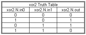
7. xor2
7.1. Description
- xor2 is slighly differet from an or gate in that if both inputs are on the output is off. If either input is on the output is on.
-
7.2. Examples
8. Signals
- -not means that you're using the inverted value, so that a low voltage on the physical pin produces a TRUE value inside HAL (instead of "positive logic" where a high voltage on the physical pin produces a TRUE value)
![[Home]](/chips.gif)