Classicladder Ver 7.124 documentation
While under development version
-
- 1. Loading options
-
- 2. The Classicladder GUI
-
- 3. Modbus
-
- 4. The Variables
-
- 5. Bugs
-
- 6. Other new items
-
-
- 6.1. Indexed or vectored variables
-
- 6.2. New timers (IEC)
-
- 6.3. AVG as well as MOY
-
- 6.4. Jump and call
-
- 6.5. %QW and %IW variables
-
- 6.6. %QF and %IF variables
-
- 6.7. %E variables
-
- 6.8. Internal file format
-
- 6.9. Development pics / text
-
This page was considered current as of Jan of 2009.The most current docs are in the LinuxCNC manual now
This page documents the features and workings of
ClassicLadder ver 7.124 available in 2.3
For info about the earlier release click here (version 7.100) ->
ClassicLadder
Classicladder is the original work of Marc Le Douarain.
Classic Ladder version 7.124 has been adapted to EMC2 and is in 2.3
1. Loading options
The realtime module is loaded much the same as before, but you can specify how many new timers you want with numTimerIec
?='number'.
Also Classicladder now has 10 each of s32 in and out pins by default .
The user module still can be loaded with the --nogui option but also has a option for loading MODBUS info.
For TCP protocol do not specify anything for MODBUS_MASTER_SERIAL_PORT=
Now you should use --modmaster instead of --config=filename to signal that you want modbus master initialized.
The modbus communications page info is now saved/loaded with everything else in a ladder program.
all possible options (you can combine most):
--nogui don't start the GUI
--config=filename initialize modbus and load modbus info from file name ( deprecated now )
--modmaster initialize modbus master support (modbus info now comes from the saved ladder program and/or modbus com page in the config window)
--modserver initialize modbus slave support (only TCP right now)
--modbus_port=portnumber used to designate the portnumber to use for TCP modbus slave (9502 is default)
--newpath used to change the path/filename after loading a program (Stepconfig uses this to load different programs but always save them as custom.plc
And of course you can specify a path/filename to load a ladder program
2. The Classicladder GUI
| This is the Section Display window | 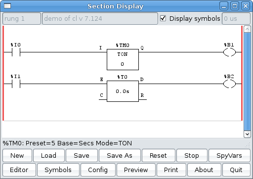 |
You might notice that there is a line under the ladder program display that reads '%TM0: Preset=5 Base=Secs Mode= TON'
That is the status bar that gives you info about elements of the ladder program that you click on.
This status line will now display HAL signal names for variables %I, %Q and the first %W (in an equation)
the vars button is for looking at variables, toggle it to display one, the other, both, then none of the windows.
Config is for configuring MODBUS and to display how many elements there are.
The rung displayed has a new timer (top) and a sorta old timer (bottom) in it. Marc changed the old timers by adding a control pin to it (C).
The way to make it work like the old timers is to connect E and C together. But this would break old programs.
The new timer (called timer_iec) is to replace the old timers and monostables.
You might see some funny labels, such as (103) in the rungs. This is displayed (on purpose) because of an old bug- when erasing elements older versions sometimes didn't
erase the object with the right code. You might have noticed that the long horizontal connection button sometimes didn't work in the older versions. This was because
it looked for the 'free' code but found something else. The number in the brackets is the unrecognized code. The ladder program will still work properly, to fix it
erase the codes with the editor and save the program.
3. Modbus
In this version Modbus is enabled.
I would like to thank Dave Keeton for his patient testing of the new MODBUS routines
And assure his wife he really was working on this - not (just?) drinking beer
Dave used an embedded controller called Cubloc (model 280 I think)
http://cubloc.com/product/01_01.php for a slave device.
I tested with a, free as in cost, PLC simulator Program ( only for windows )
http://www.plcsimulator.org/index.html
and my Yaskawa P7 VFD drive
Things to consider:
Modbus is a userspace program so it might have latency issues on a heavily laden computer
Modbus is not really suited to Hard real time events such as position control of motors or to control E-stop.
The classicladder GUI must be running for Modbus to be running.
Modbus is not fully finished so it does not do all modbus functions.
To get MODBUS to initialize you must specify that when loading the classicladder userspace program
eg. loadusr -w classicladder --modmaster myprogram.clp
(assuming myprogram.clp is present -w makes HAL wait till you close classicladder before closing realtime session)
my idea behind this is to get a working modbus solution out there then we can decide how it should be done in the best way.
As it stands now classicladder also loads a TCP modbus slave (if you add --modserver on comand line) - I have not tested this nor have I tested the TCP modbus master.
I have done some testing with the serial port and had to add some functions to get it to talk to my VFD -but it does work.
Modbus function 1,2,3,4,5,6,8,15,16 (read coils,read inputs, read holding registers, read input registers, write single coils, write single register, echo test, write multiple coils, write multiply registers) are currently available.
If you do not specify a --modmaster when loading the classicladder user program this (next) page will not be displayed.
|
 SERIAL PORT            -  For IP -blank
                        -  For serial - the location/name of serial driver eg. /dev/ttyS0 ( or /dev/ttyUSB0 for a USB to serial converter )
 SERIAL SPEED           -  Should be set to speed the slave is set for - 300, 600, 1200, 2400, 4800, 9600, 19200, 38400, 57600, 115200 are supported.
 PAUSE AFTER TRANSMIT   -  Pause (milliseconds) after transmit and before receiving answer -some devices need more time (eg usb-serial converters)
 PAUSE INTER-FRAME      -  Pause (milliseconds) after receiving answer from slave- this sets the duty cycle of requests (it's a pause for EACH request)
 REQUEST TIMEOUT LENGTH -  Length (milliseconds) of time before we decide that the slave didn't answer.
 MODBUS ELEMENT OFFSET  -  used to offset the element numbers by 1 (for manufacturers numbering differences)
 DEBUG LEVEL            -  Set this to 0-3 (0 to stop printing debug info besides no-response errors).
 READ COILS/INPUTS MAP TO- Select what variables that read coils/inputs will update. (B or Q)
 WRITE COILS MAP TO      -  Select what variables that write coils will updated.from (B,Q,or I)
 READ REGISTERS/HOLDING   - Select what variables that read registers will update. (W or QW)
 WRITE REGISTERS MAP TO   - Select what variables that read registers will updated from. (W, QW, or IW)
 SLAVE ADDRESS          -  For serial-The slaves ID number usually settable on the slave device (usually 1-256)
                        -  For IP -The slave IP address plus optionally the port number.
 TYPE ACCESS            -  This selects the MODBUS function code to send to the slave (eg what type of request)
                                  Coils/inputs are read/written to I, B, or Q variables (user selects)
                                  registers and holding registers map to W, IW, or QW variables (usr selects)
 1st MODBUS ELEMENT     -  The address (or register number)  of the first element in a group. (remember to set MODBUS ELEMENT OFFSET properly)
 NUMBER OF ELEMENTS     -  The number of elements in this group
 LOGIC                  -  You can invert the logic here
 1st%I%Q IQ WQ MAPPED   -  This is the starting number of %B, %I, %Q, %W, %IW, or %QW variables that are mapped onto/from the modbus element group
                                  (starting at the first modbus element number)
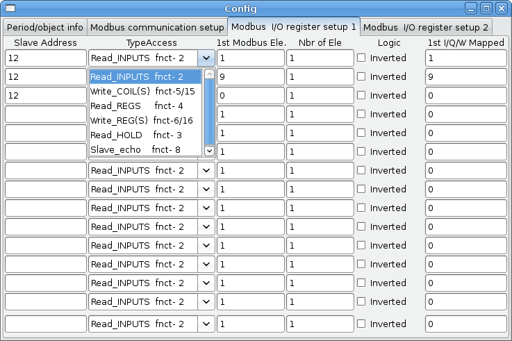
In the example above:
Port number- for my computer /dev/ttyS0 was my serial port
The serial speed is set to 9600 baud.
Slave address is set to 12 ( on my VFD I can set this from 1-31, meaning I can talk to 31 VFDs maximum on one system)
The first line is set up for 8 input bits starting at the first register number (register 1) so register numbers 1-8 and maps them on to
Classicladder's %B variables starting at %B1 ending at %B8.
The second line is set for 2 output bits starting at the ninth register number (register 9) so register numbers 9-10 and maps them on to classicladder's %Q variables starting at %Q9 ending at %Q10.
The third line is set to write 2 registers (16 bit each) starting at the 0 th register number (register 0) so register numbers 0-1 and maps them on to classicladder's %W variables starting at %W0 ending at %W1
It's easy to make an off-by-one error as sometimes the modbus elements are referenced starting at one rather then 0 (actually by the standard that is the way it's supposed to be!) You can use the modbus element offset radio button to help with this.
The documents for your modbus slave device will tell you how the registers are set up- there is no standard way.
The SERIAL PORT, PORT SPEED, PAUSE, and DEBUG level are editable for changes (when you close the config window values are applied though Radio buttons apply immediately)
To use the echo function select the echo function and add the slave number you wish to test. You don't need to specify any variables.
The number 257 will be sent to the slave number you specified and the slave should send it back. you will need to have classicladder running in a terminal to see the message.
serial
Classicladder uses RTU protocol (not ASCII)
The default settings are:8 data bits ,No parity is used. and 1 stop bit also know as 8-N-1
Its is possible to change these be hand editing the saved ladder (.clp) file. (GUI additions to follow after testing of new settings)
Baud rate must be the same for slave and master. Classicladder can only have one baud rate so all the slaves must be set to the same rate.
Pause inter frame is the time to pause after receiving an answer.
MODBUS_TIME_AFTER_TRANSMIT is the length of pause after sending a request and before receiving an answer (this apparently helps with USB converters which are slow)
This is from Marc's read me:
HARDWARE (DISTRIBUTED INPUTS/OUTPUTS)...
ClassicLadder can use distributed inputs/outputs on modules using the modbus
protocol ("master": pooling slaves).
The slaves and theirs I/O can be configured in the config window.
2 exclusive modes are available : ethernet using Modbus/TCP and serial using Modbus/RTU.
No parity is used.
If no port name for serial is set, IP mode will be used...
The slave address is the slave address (Modbus/RTU) or the IP address.
The IP address can be followed per the port number to use (xx.xx.xx.xx:pppp) else
the port 9502 will be used per default.
2 products have been used for tests: a Modbus/TCP one (Adam-6051, http://www.advantech.com)
and a serial Modbus/RTU one (http://www.ipac.ws)
See examples: adam-6051 and modbus_rtu_serial.
Web links: http://www.modbus.org and this interesting one: http://www.iatips.com/modbus.html
MODBUS TCP SERVER INCLUDED
ClassicLadder has a Modbus/TCP server integrated. Default port is 9502, standard 502 requires that the application has been launched with root privileges.
List of Modbus functions code supported are: 1, 2, 3, 4, 5, 6, 15 and 16.
Modbus bits and words correspondence table is actually not parametric and correspond directly to the %B and %W variables.
Infos on modbus protocol are available here:
http://www.modbus.org
http://www.sourceforge.net/projects/jamod
http://www.modicon.com/techpubs/toc7.html
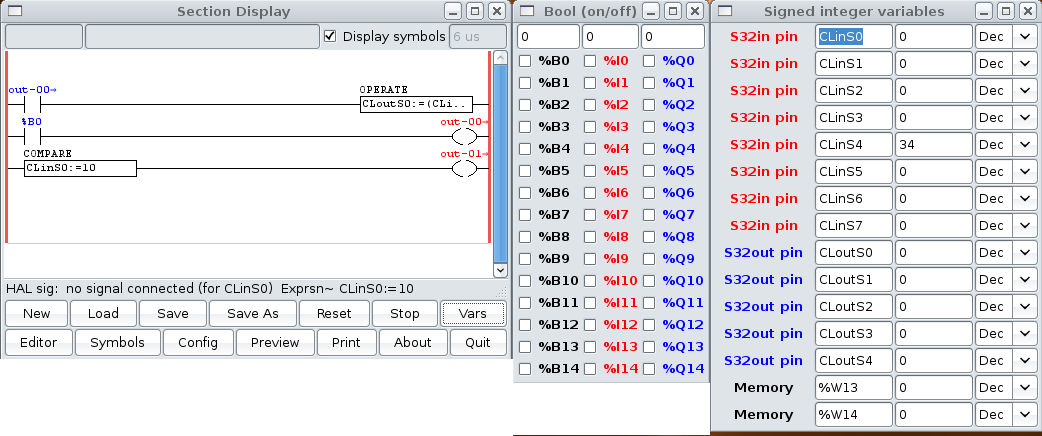
4. The Variables
These Variables are used in COMPARE to get information about, or change specs of, ladder objects
Such as changing a counter preset, or seeing if the a timer is done running.
List of variables :
Bxxx : Bit memory xxx (boolean)
Wxxx : Word memory xxx (32 bits integer)
Txx,R : Timer xx running (boolean, user read only)
Txx,D : Timer xx done (boolean, user read only)
Txx,V : Timer xx current value (integer, user read only)
Txx,P : Timer xx preset (integer)
TMxxx.Q timer xxx done (read )
TMxxx.P timer xxx preset (read write)
TMxxx.V timer xxx value (read write)
Mxx,R : Monostable xx running (boolean)
Mxx,V : Monostable xx current value (integer, user read only)
Mxx,P : Monostable xx preset (integer)
Cxx,D : Counter xx done (boolean, user read only)
Cxx,E : Counter xx empty overflow (boolean, user read only)
Cxx,F : Counter xx full overflow (boolean, user read only)
Cxx,V : Counter xx current value (integer)
Cxx,P : Counter xx preset (integer)
Ixxx : Physical input xxx (boolean) - connects to HAL input bit -
Qxxx : Physical output xxx (boolean) - connects to HAL output bit -
IQxxx : Connects to HAL s32 input pins
QWxxx : Connects to HAL s32 output pins
IFxxx : Connects to HAL float input pins
QFxxx : Connects to HAL float output pins
Xxxx : Activity of step xxx (sequential language)
Xxxx,V : Time of activity in seconds of step xxx (sequential language)
Exx :Error variable there are max 10 (0-9) 0 is used internally for modbus com errors
5. Bugs
- In compare blocks the function %W=ABS(%W1-%W2) is accepted but does not compute properly. only %W0=ABS(%W1) is currently legal
- When loading a ladder program it will load modbus info but will not tell classicladder to initialize modbus. You must initialize modbus when you first load the GUI by adding --modmaster
- If the section manager is placed on top of the section display, across the scroll bar and exit is clicked the user program crashes.
- When using --modmaster you must load the ladder program at the same time or else only TCP will work.
- reading/writing multiply registers in modbus has checksum errors
- It seems sometimes when saving the modbus port name the data is saved corrupted...the work around is to edit the .clp file by hand.
6. Other new items
6.1. Indexed or vectored variables
Variables indexed with a variable are now available. Some might call this vectored variables.
Example: %W0[%W4] => if %W4 equals 23 it corresponds to %W23
6.2. New timers (IEC)
There are new timer that are IEC compliant.
There are three modes - TON, TOF, TP.
TON when timer input is held true, sets output true after countdown is done and as long as timer input is still true.
TOF When timer input is held true, sets output true till the input is false then the timer counts down and sets output false.
TP when timer input is pulsed true or held true timer sets output true till timer counts down. (one-shot)
The time intervals can be set in multiples of 100ms, seconds, or minutes.
- Variables for IEC TIMERS are:
%TMxxx.Q timer done (read)
%TMxxx.P timer preset (read write)
%TMxxx.V timer value (read write)
6.3. AVG as well as MOY
In math expressions you can use AVG (average) instead of MOY (moyenne a French word for average)
6.4. Jump and call
Jump coils and call coils now work properly-you can have multiple call coils in one rung
6.5. %QW and %IW variables
Classicladder now uses %IW and %QW variables to connect to s32 in and out pins instead of mapping on top of %W variables.
The default number is 10 each.
6.6. %QF and %IF variables
Classicladder now can connect to float pins. Classicladder does not yet internally handle floats, so it cuts the floating point
off leaving an integer. Allows connections to float pins with out using a conversion component.
The default number is 10 each.
6.7. %E variables
%E variable are intended for internal error tracking.
For now there are 10 %E variables
%E0 is for Modbus communication errors
you can read and write %E variables just like regular bit variables except the reserved ones will also be controlled by CL
6.8. Internal file format
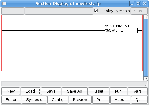
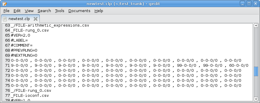
This file represents the ladder rung above.
Each line of numbers represent a line in the rung
each group is sorted as so: element type, connection with top, variable type / variable number.
looks like 0,0,0/0
You can see that the second line starts with 9 for 7 groups then 99 for two then 60
9 stands for horizontal connection, 99 is used block and 60 is assignment block.
In the assignment block group (60,0,0/0) the variable type is always 0, the last number (variable number) is the line number in the arithmetic_expressions section.(starts at 0 but any number can be missing if it is erased
Here is a list of elements right from the source code:
/* elements in the rungs */
- define ELE_FREE 0
- define ELE_INPUT 1
- define ELE_INPUT_NOT 2
- define ELE_RISING_INPUT 3
- define ELE_FALLING_INPUT 4
- define ELE_CONNECTION 9
- define ELE_TIMER 10
- define ELE_MONOSTABLE 11
- define ELE_COUNTER 12
- define ELE_TIMER_IEC 13
- define ELE_COMPAR 20
- define ELE_OUTPUT 50
- define ELE_OUTPUT_NOT 51
- define ELE_OUTPUT_SET 52
- define ELE_OUTPUT_RESET 53
- define ELE_OUTPUT_JUMP 54
- define ELE_OUTPUT_CALL 55
- define ELE_OUTPUT_OPERATE 60
/* for complex elements using many blocks : only one block
is "alive", others are marked as UNUSABLE */
- define ELE_UNUSABLE 99
- define ELE_NO_DEFAULT_NAME 255
/* used only for edit */
- define EDIT_CNX_WITH_TOP 100
- define EDIT_POINTER 101
- define EDIT_LONG_CONNECTION 102
- define EDIT_ERASER 103
Here is a ist of variables:
/* Type of vars */
/* booleans */
- define VAR_MEM_BIT 00
- define VAR_TIMER_DONE 10
- define VAR_TIMER_RUNNING 11
- define VAR_TIMER_IEC_DONE 15
- define VAR_MONOSTABLE_RUNNING 20
- define VAR_COUNTER_DONE 25
- define VAR_COUNTER_EMPTY 26
- define VAR_COUNTER_FULL 27
- define VAR_STEP_ACTIVITY 30
- define VAR_PHYS_INPUT 50
- define VAR_PHYS_OUTPUT 60
- define VAR_ERROR_BIT 70
- define VAR_ARE_WORD 199 /* after it, all vars are no more booleans */
/* integers */
- define VAR_MEM_WORD 200
- define VAR_STEP_TIME 220
- define VAR_TIMER_PRESET 230
- define VAR_TIMER_VALUE 231
- define VAR_MONOSTABLE_PRESET 240
- define VAR_MONOSTABLE_VALUE 241
- define VAR_COUNTER_PRESET 250
- define VAR_COUNTER_VALUE 251
- define VAR_TIMER_IEC_PRESET 260
- define VAR_TIMER_IEC_VALUE 261
- define VAR_PHYS_WORD_INPUT 270
- define VAR_PHYS_WORD_OUTPUT 280
here is another sample:


- Modifications done for EMC
There are many changes to adapt classicladder foe EMC see the zEMC_README.txt for a (hopefully) complete summary
As for important to the user changes:
       -Hal signal names are displayed in the status bar when objects are clicked on (if the object can have a signal name)
       -Hal signal names are displayed in the symbols window
6.9. Development pics / text
       - The classicladder userspace program should check that the realtime module has loaded enough ladder elements for the program requested.
         This should be fairly easy as classicladder already saves ladder element numbers with ladder programs.
         I keep thinking that the userspace program should load the realtime program this would simplify some things-but break configs.
       - A button that loads a text reader that displays a description of a ladder program would be nice.
         It could also have pages for basic info such as variable names and explanations of ladder elements-
         like a help screen I guess. I like self documenting programs.
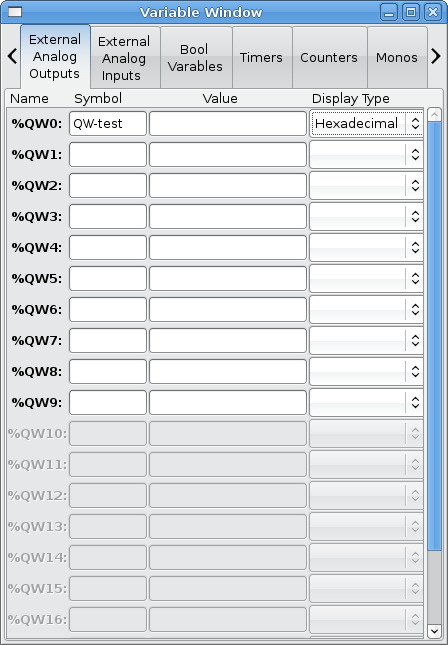
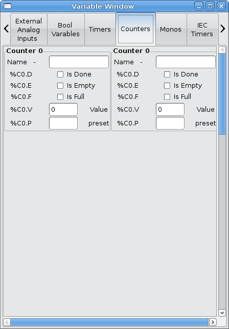
Here's a test screen shot of a variable window made with glade for CL:

![[Home]](/chips.gif) ClassicLadder Ver 7.124
ClassicLadder Ver 7.124