|
Contact me Chris Morley c/o the EMC users maillist-I'll try to help |
|
Contact me Chris Morley c/o the LinuxCNC users maillist-I'll try to help |
|
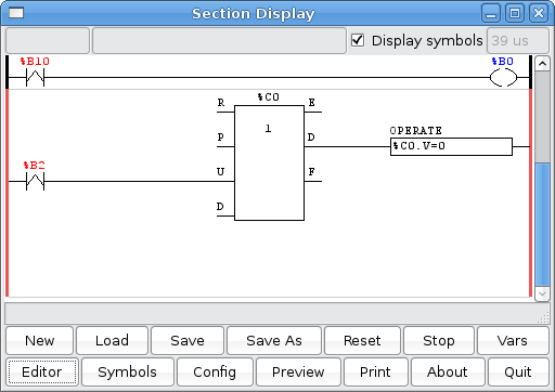
|| This is a program for a tool turret. The turret has a home switch at tool position 1 and another another switch to tell you when the turret is in a lockable position. To keep track of the actual tool number one must count how many positions past home you are. We will use Classicladder's counter block '$CO'.The counter is preset to 1 when RESET is true. The counter is increased by one on the rising edge of INDEX. We then 'COMPARE' the counter value (%C0.V) to the tool we want (in the example only checks for tool 1 and 2 are shown). We also 'OPERATE' the counter value to a word variable (%W0) that (you can assume) is mapped on to a S32 out HAL pin so you can let some other HAL component know what the current tool number is. In the real world another S32 (in) pin would be used to get the requested tool number from EMC.You would have to load Classicladder's realtime module specifying that you want S32 in and out pins. See 'loading options' above.|| 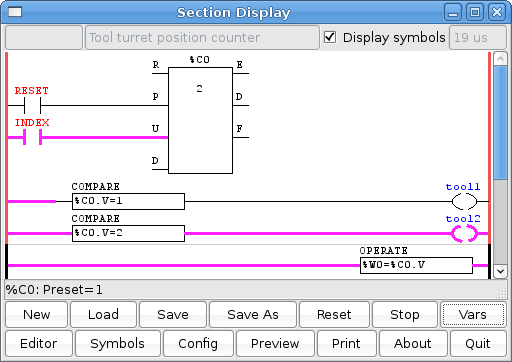 || || |
|
|| This is a program for a tool turret. The turret has a home switch at tool position 1 and another another switch to tell you when the turret is in a lockable position. To keep track of the actual tool number one must count how many positions past home you are. We will use Classicladder's counter block '$CO'.The counter is preset to 1 when RESET is true. The counter is increased by one on the rising edge of INDEX. We then 'COMPARE' the counter value (%C0.V) to the tool we want (in the example only checks for tool 1 and 2 are shown). We also 'OPERATE' the counter value to a word variable (%W0) that (you can assume) is mapped on to a S32 out HAL pin so you can let some other HAL component know what the current tool number is. In the real world another S32 (in) pin would be used to get the requested tool number from LinuxCNC.You would have to load Classicladder's realtime module specifying that you want S32 in and out pins. See 'loading options' above.|| || |
|
These last two rungs work together. The job of the seventh rung is to either terminate the tool change (if homed) or terminate the test move (if homing). First check that stepgen has been sent a command (B0 set), then that the tool is in position (I2 set), and IF homed (B1 set) then tell EMC that the tool chang is done (Q0) and also reset the flag that indecates tool change is still in progress (B2). Note that if the first two checks pass (B0 and I2), then B0 is reset deactivating this whole rung. This brings us to B3, which involves the last rung. |
|
These last two rungs work together. The job of the seventh rung is to either terminate the tool change (if homed) or terminate the test move (if homing). First check that stepgen has been sent a command (B0 set), then that the tool is in position (I2 set), and IF homed (B1 set) then tell EMC that the tool change is done (Q0) and also reset the flag that indicates tool change is still in progress (B2). Note that if the first two checks pass (B0 and I2), then B0 is reset deactivating this whole rung. This brings us to B3, which involves the last rung. |
|
The job of the eigth and final rung is to lock the turret at each tool position tried while homing. This rung only comes into play when homing, after that it is not used again. So, if stepgen has finished (B0 reset), and if NOT homed (B1 reset), then trip a timer that brings B3 TRUE long enough for the turret to lock. B3 is then used in several rungs to put a hold on things while the index mark is checked. Going back up the rungs, in rung seven B3 is used to disable stepgen by dropping out Q3 (stepgen.2.enable), in rung six it disables the whole rung, in rung one it deactivates the drive amp and locks the turret. |
|
The job of the eighth and final rung is to lock the turret at each tool position tried while homing. This rung only comes into play when homing, after that it is not used again. So, if stepgen has finished (B0 reset), and if NOT homed (B1 reset), then trip a timer that brings B3 TRUE long enough for the turret to lock. B3 is then used in several rungs to put a hold on things while the index mark is checked. Going back up the rungs, in rung seven B3 is used to disable stepgen by dropping out Q3 (stepgen.2.enable), in rung six it disables the whole rung, in rung one it deactivates the drive amp and locks the turret. |
|
If you are using Linuxcnc 2.5 or better use the command G10 L20 P0 Z.250 P0 means use the current coordinate system |
|
If you are using LinuxCNC 2.5 or better use the command G10 L20 P0 Z.250 P0 means use the current coordinate system |
If you have a common/interesting ladder program please add it.
if you need help adding it or help creating a special ladder program
Contact me Chris Morley c/o the LinuxCNC users maillist-I'll try to help
They may or may not be actually tested with hardware.
| Some basic concepts The first line shows a latching output that uses momentary switches to turn it on and off. When the 'normally open' B1 contact is momentarily on, It allows 'power' to coil Q0. This in turn closes contact Q0, which jumps 'power' across the B1 contact essentially removing it's influence and 'latching' the output coil. To turn the coil off one must momentarily open the 'normally closed' B0 contact which supplies 'power' to the whole line. If you are a logic kinda guy the line says If B0 is off AND either B1 OR Q0 is on then coil Q0 is on. The second, third, and fourth line are examples of using variables in compare and operate elements. The second line starts with a 'rising-edge' contact, B2 which supplies 'power' to an operate element. A rising edge contact allows power thru it only as it changes from off to on. The operate block adds 1 to the current value in variable W0, then stores it back in variable W0. The third line uses a compare element to preform a math function 'modulus'. The element takes the number stored in W0 divides it by two then compares if the remainder is NOT equal to 0. It breaks down like this: %W0 is a variable, % means modulus, 2 is the number to divide, <> is NOT equal , 0 is the number we want to compare to. If the compare element is true (meaning the modulus of W0 is not = 0) then the Q1 coil is turned on. Using the modulus math, this line checks to see if the number stored in W0 is odd.The fourth line is essentially the same, though it uses the = sign and if the compare is true it will turn Q2 on. This line checks to see if W0 is even. If you programmed this ladder program and turned B0 on and off a bunch of times (by clicking on the B0 checkbox in the variable window) Q1 and Q2 would turn on and off alternately and if you displayed the signed variable window you would see the count of variable W0. |  |
| This is a program for a tool turret. The turret has a home switch at tool position 1 and another another switch to tell you when the turret is in a lockable position. To keep track of the actual tool number one must count how many positions past home you are. We will use Classicladder's counter block '$CO'.The counter is preset to 1 when RESET is true. The counter is increased by one on the rising edge of INDEX. We then 'COMPARE' the counter value (%C0.V) to the tool we want (in the example only checks for tool 1 and 2 are shown). We also 'OPERATE' the counter value to a word variable (%W0) that (you can assume) is mapped on to a S32 out HAL pin so you can let some other HAL component know what the current tool number is. In the real world another S32 (in) pin would be used to get the requested tool number from LinuxCNC.You would have to load Classicladder's realtime module specifying that you want S32 in and out pins. See 'loading options' above. | |
Ins

spindle orient complete
magazine in
spindle unclamp
magazine down
magazine up
spindle clamped
magazine out
counter switch
tool 1 position switch(for homing purposes)

Outs

orient spindle
magazine in   (remove power and the magazine will move out)
unclamp spindle   (remove power and the spindle will clamp)
lower magazine    (remove power and the magazine will go up)
rotate magazine cw
rotate ccw
It was desired that the turret be able to rotate either direction, taking the shortest route to the next tool. It was also desired that the turret would auto-home upon the first tool call after power up. Actually I wanted to save the tool number and read it back in after power up, but have not figured out how to do that yet. The homing sequence consists of blindly unlocking, moving one tool position, locking, and checking for the index pin to be true, if not, keep going. Once tool one is found, it then proceeds normally to the tool that was called. The ladder code does NOT keep track of what the current tool number is, rather it relies on EMC to supply this information to it.
A video of the turret in action can be found at http://mackintoshweb.com/pub/video/turret.flv
First some background:
This example uses the parallel ports (parport) to communicate with the machine. Here are the relevant lines from the main hal file:
net tstep <= stepgen.2.step => parport.1.pin-17-out
net tdir <= stepgen.2.dir => parport.1.pin-16-out
and here are the relevant lines from the post-gui hal file:
net tool-z-select classicladder.0.out-01 => parport.1.pin-14-out
net tool-lock classicladder.0.out-02 => parport.1.pin-06-out
net tencoder-z parport.0.pin-10-in => classicladder.0.in-04
Note that last line, there is a quadrature encoder on the turret, but the A and B channels are not working, so until I replace it, only the index channel is available, but that seems to be enough.
If you are wondering what tool-z-select is all about, my machine shares one drive amp between the Z axis and the tool turret motor. So this signal activates a set of relays that change from the Z axis step/direction inputs to the Turret step/direction inputs and changes the output of the drive amp from the Z axis motor to the turret motor. Looking back, I probably could have combined the relay set and turret lock, but I did not, and it works, so it stays.
The rest of the communications is with EMC:
Everything is in the post-gui hal file, here are the relevant lines:
net tool-prepare-loopback iocontrol.0.tool-prepare => iocontrol.0.tool-prepared
net tool-change-start iocontrol.0.tool-change => classicladder.0.in-00
net tool-change-done classicladder.0.out-00 => iocontrol.0.tool-changed
net tpos-cmd classicladder.0.floatout-00 => stepgen.2.position-cmd
net tpos-cmd => near.1.in1
net tpos-fb stepgen.2.position-fb => near.1.in2
net tpos-fb => abs.0.in
net tpos-fb-abs abs.0.out => sum2.0.in1
net tpos-fb-rounded sum2.0.out => classicladder.0.floatin-00
net tpos-fb-sign abs.0.sign => classicladder.0.in-03
net tpos-inpos near.1.out => classicladder.0.in-02
net tenable classicladder.0.out-03 => stepgen.2.enable
net tnum-current iocontrol.0.tool-number => classicladder.0.s32in-00
net tnum-next iocontrol.0.tool-prep-number => classicladder.0.s32in-01
Note the above use of near, abs, and sum2, these were needed to do some prep work on some of the inputs.
Some other related things from the main hal file are:
setp near.1.difference 0.0001
setp sum2.0.in0 0.5
setp sum2.0.offset 0.0
setp stepgen.2.position-scale 500
setp stepgen.2.steplen 10
setp stepgen.2.stepspace 10
setp stepgen.2.dirhold 10
setp stepgen.2.dirsetup 10
setp stepgen.2.maxaccel 8
setp stepgen.2.maxvel 4.0
Now some explanation of what is being done, then after that the ladder code...
Stepgen.2 is configured in terms of tool units, it takes 500 steps to move one tool position. Thus, a command of '3' will move to tool position 3. The system does not know how many positions the turret really has, thus a command of '3+n*8', where 'n' is some integer, positive or negative, will also call tool 3 as there are 8 positions on my tool turret.
Another interesting point is that stepgen is commanded in absolute terms, but what is needed for the turret is relative movement. That is, what is needed is not to say 'go to tool 5', but rather ' go backward/forward 2 tool slots to get to the needed tool.'. So internal to the ladder, this incremental move is calculated, then added to the current position feedback from stepgen to come up with the nearest absolute position that will equate to the needed tool. Thus the absolute number given/received to/from stepgen is really meaningless.
The reason for the use of near is because when float numbers are taken into classicladder they are truncated to a signed 32 bit integer. Note that they TRUNCATED, not rounded! Thus a value of 0.99999 becomes zero! not 1... this messes every thing up as the numbers given by stepgen rarely are exactly what was commanded, but may differ either way by some minute amount. If the minute error is in one direction, no problem, but if it is in the other direction the result will be off by one from what was commanded. Like 3.9999999 becomes 3 instead of 4. So instead of monitoring stepgen's feedback directly to know when the commanded move is done, the output of near is monitored. The inputs to near are stepgen's commanded position and it's feedback.
The reason for the use of abs and sum2 is similar to the reason for the use of near, that is, a rounded version of stepgens feedback position is needed inside the ladder code. So this takes the absolute value of the feedback, adds 0.5 to it, thus achieving a rounded value after truncation, and passes this into classicladder along with the sign of the original feedback.
This brings up the obvious question: Why not look at this rounded version of the feedback and not use near. This could be done, the reason it was not is because this ladder grow a bit at a time, and the bit using near was already in place and working before the bit using abs/sum2 came into existence.
Now a look at the ladder code that ties all this stuff together and makes it work:
Here are the fist two rungs:
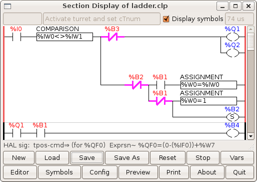
The first rung is mainly used to unlock the turret (Q2) and change over the drive amp (Q1), as mentioned above. IW0 is the current tool number (from tnum-current) and is compared to IW1, the needed tool number (from tnum-next), to make sure they are not the same, as there is no need to go where one already is. Hay, that sounds like an ancient Chinese proverb. I0 (from tool-change-start) indicates that a tool change request has been made. B3 only comes into play while homing the turret, once homed it can be ignored. Homing will be explained later, B3 is explained last. W0 is an internal copy of the current tool number, or in the case of homing is set to one, as the current tool upon completion of the homing operation will be tool one, although IW0 will be zero upon the first tool call. B2 is a flag that notes homing is in progres. B1 is a flag that when set indicates the turret is homed. Note that as soon as B2 is set, the whole lower leg of the rung is disconnected by the N.C. B2 contact, as this stuff needs to be done only once to get the ball rolling.
The second rung is used to disable the normal movement calculations (rungs 3 and 4) during homing. It was only needed due to the limited width of the rungs which was just too narrow to allow Q1/B1 contacts to replace the B4 contacts in the next two rungs.
Speaking of the next two rungs:

These could have been one rung, but for limited space on each rung. These, if enabled (B4), compute the shortest relative move to get from the current tool to the needed tool. The are two hard coded numbers of interest here, 8 and 4, 8 is the number of positions on my turret, change this as needed for your turret, 4 is half the number of positions, again change as needed. W7 is the steps in the relative move to be made. B0 is a flag that says W7 is ready.
If your turret has an odd number of positions, then the above 4s in one rung would be different from the ones in the other rung by one, as an odd number does not half evenly.
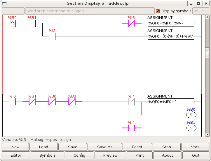
Once W7 is ready, the fifth rung comes active on the rising edge of B0, IF HOMED (B1 set), and adds W7 to stepgen's current position feedback (IF0), taking into account the sign of the feedback position (I3), and outputs this as stepgen's new commanded position (QF0).
There is also a bug work-around here, the assignment will choke and return zero if negation is used in certain ways. Namely '%QF0=-%IF0+%W7' will fail, I tried several things and then found that '0-(%IF0)' took care of it.
The sixth rung is all about homing, once homed (B1 set) it no longer comes into play. It checks that a tool change has been called (I0), that the turret is NOT homed (B1 not set), that stepgen still needs to be told were to go (B0 not set), and that the turret is not currently locked (B3 not set). When homing, the turret will lock at each tool tried while checking for the index marking tool one. The final check is to look for the index mark (I4) at tool one. If no index mark, then just tell stepgen to move one more position and set B0 to get things moving again. If the index mark (I4) is high/true, then set the homed flag (B1). Once B1 is set, this means the turret is homed and it stays set as long as EMC is running. Should one for some reason want to re-home the turret, one need only reset B1 (manual intervention) and make a tool change call.
Note that once homing is done (B1 set), the turret is at T1, which may or may not be the tool that was called. In either event, the ladder code now makes a final move to the tool that was called, even if that tool is tool one. Thus if the tool called was tool one, there will be a final turret activation but no movement, just the clanck-clanck of the lock. That is what happens when you go to where you already are. :)
That brings us to the last two rungs:

These last two rungs work together. The job of the seventh rung is to either terminate the tool change (if homed) or terminate the test move (if homing). First check that stepgen has been sent a command (B0 set), then that the tool is in position (I2 set), and IF homed (B1 set) then tell EMC that the tool change is done (Q0) and also reset the flag that indicates tool change is still in progress (B2). Note that if the first two checks pass (B0 and I2), then B0 is reset deactivating this whole rung. This brings us to B3, which involves the last rung.
When the tool change is done, EMC is notified via Q0, but the turret is NOT directly deactivated in the ladder code. Rather, once Q0 is set, telling EMC the tool change is done, EMC then reset it's iocontrol.0.tool-change, thus resetting I0, deactivating the whole first rung and locking the turret as well as deactivating rung five which keys on I0. Note that in this rapid chain reaction that Q0 is only set for a brief moment.
The job of the eighth and final rung is to lock the turret at each tool position tried while homing. This rung only comes into play when homing, after that it is not used again. So, if stepgen has finished (B0 reset), and if NOT homed (B1 reset), then trip a timer that brings B3 TRUE long enough for the turret to lock. B3 is then used in several rungs to put a hold on things while the index mark is checked. Going back up the rungs, in rung seven B3 is used to disable stepgen by dropping out Q3 (stepgen.2.enable), in rung six it disables the whole rung, in rung one it deactivates the drive amp and locks the turret.
That is it, I hope someone finds this useful. If there are any questions or comments on it, please email me. Note that I sometimes go a month or more without checking my email, though mostly I check it about once a week.
I wish to give credit to all those on the IRC channel (#emc) who have helped me with figuring out not just the tool turret, but other things as well. I do not remember who everyone is, but thank you all.
Terry Mackintosh <terry@mackintoshweb.com>
If you email me, note that I use ASK (Active Spam Killer), so you will need to reply to a confirmation email before I will ever see your email. The message is auto-deleted if not confirmed within ten days.
| This is a program to do tool probing / touch-off in MDI mode by pressing a single button %I0 connects to a PYVCP button %I1 connects to "halui.mode.is_mdi' pin %I2 connects to 'motion.motion-inpos' pin %Q0, %Q1, and %Q2 each connect to 'halui.mdi-command-XX' where XX is 00, 01, and 02 respectively. |  |
In your ini file under [HALUI] you add MDI_COMMAND = G38.2 Z-3 F16 and MDI_COMMAND = G92 z .250 and MDI_COMMAND -G0 z 1
If you use only one coordinate system (eg G54) it would be better to use G10 L20 P1 Z.250 instead of the G92 command.
If you are using LinuxCNC 2.5 or better use the command G10 L20 P0 Z.250 P0 means use the current coordinate system
G92 adds a second offset to ALL coordinate systems which can be confusing. The G10 changes only the coordinate you choose (eg P1 = G54 system)
The logic goes like this when the PYVCP button is on and emc is in MDI mode and %B0 and %B1 are not on set %B0 output on. %B0 and %B1 outputs represent procedure steps.
Next line when B0 turns on a monostable holds the signal on for 500 ms which turns on Q0 (which connects to HALUI MDI command 0-G38.2 z-3 f16 -probe down in z at feed rate 16 till contact is made)
Next line: When %B0 is on (step 0 is active) and %I2 (in position signal-means probe is done.) goes off-to-on then set %B1 (step 1) on.
Next line: When %B1 is on, turn on a monostable for 500 ms that holds %Q1 on (%Q1 controls MDI command G92 .250 set offset so z = zero at the bottom of the .250 thick plate )also a timer is set to run.
When the timer is done use a monostable to hold %Q2 on for 500 ms (MDI command Go z 1 -rapid away from plate) and reset %B1 (step1 done)& %B0 (step0 done).
The timer is used to make sure the last rapid command is actually last-there isn't a pin to tell you when the G92 command has finished.
Here is a link to the thread http://www.cnczone.com/forums/showthread.php?t=62423 Below is what one user used for a touch-off plate. Here is the Video...http://www.youtube.com/watch?v=QYBAH6E8IZs
If used on EMC 2.3.X a pin name needs to be changed: moton.motion-inpos to motion.in-position
Also, The timer block has changed in 2.3. The block has 4 pins
labled E,C,D,R. Pins C and E must be connected together as noted here: http://wiki.linuxcnc.org/cgi-bin/wiki.pl?UPDATING#Classicladder_changes
here is the latest ladder program:
upload:touch_off_buttons.clp

| This is the ladder program for the THC plasma config example in EMC2 It was created using Trunk from circa pre EMC 2.1/classicladder 7.100 (text and drawing snipped/borrowed from another wiki page) see: http://wiki.linuxcnc.org/uploads/dallur-thc-design.txt for full txt |  |
		There are 3 rungs in this ladder, the first one is the state-aware estop with external triggers, this circuit
		is just a slightly modified example from the classicladder example, see:
			http://wiki.linuxcnc.org/cgi-bin/wiki.pl?Sample_HAL_And_ClassicLadder
		Rung 1
			The only difference from the example is the addition of B0 which is a signal to enable rung 3 to trigger an estop
		Rung 2 is used to control the LockPierceHeight? (Q7) and MoveZtoPierceHeight?(Q8), the first circuit is activated
			by the SpindleON/TorchON? (I5) request from the user or gcode, next we check if the FloatSwitch? is on because the
			only time we want to LockPierceHeight? and MoveZtoPierceHeight? is when the float switch has been triggered.
			If LockPierceHeight? is already active we know that the FloatSwitch? has been triggered since SpindleON/TorchON?(I5)
			was last set so we can bypass the FloatSwitch? (I3) check.
			However we only want to do this for the first time the FloatSwitch? is triggered so we put in a timer which is not
			reset until the I5 or I3 signals are reset with a bypass that retains the circuit for as long as MoveZtoPierceHeight? (Q8)
			is active, MoveZtoPierceHeight? is disconnected as soon as TorchIsAtPierceHeight? (I7) is true, TorchIsAtPierceHeight?
			is external to the ladder but it is a compare (comp) which is true if the CurrentPosition? is >= PierceHeight?.
			LockPierceHeight? (Q7) is set to active every time the circuit is activated, the second circuit then deactivates
			LockPierceHeight? (Q7) when ever SpindleON/TorchON? I5 is turned off.
				To recap, If TorchON? requested and FloatSwitch? Active or LockPierceHeight? active MoveZtoPierceHeight?
				until TorchIsAtPierceHeight? then LockPierceHeight? stays active until TorchOFF? at which time it is tuned off.
		Rung 3 is used to control moveZtoFloat? (Q3), moveZtoSafe? (Q4), feed-hold (Q6) and turn_torch_on (Q5).
			The first circuit is used to determine if the mode is manual or auto, if automatic mode is on
			it means we are running gcode and in that scenario we want to move the Z torch to a safe location
			when SpindleON/TorchON? (I5) is not being requested, the main purpose of this is to keep the torch safe when moving it
			around so it will not run into uneven surfaces.
			The second circuit is a bit complex due to the nature of the initialization sequence.
				Branch 1
					If SpindleON/TorchON? (I5) is requested and ArcOK?(I4) activate feed-hold (Q6) until the PierceDelay?(I8)* timer is up.
					We want to hold the gcode execution until the pierce timer is elapsed and we have pierced through the material.
				Branch 2
					If SpindleON/TorchON? (I5) on requested and If ArcOK? is is false we activate feed-hold(Q6), reset moveZtoSafe? (Q4)
					to disable it, and activate moveZtoFloat? (Q3) until float-switch (I3) is on activated.
					If TorchIsAtPierceHeight? (I7) becomes true it will activate turn_torch_on (Q5) which will open up an alternative
					path so it will remain open until SpindleON/TorchON? (I5) turns off.
Branch 3
					If SpindleON/TorchON? (I5) is requested and if turn_torch_on (Q5) is active we start a timer set by the
					ArcStartTimeout?(I9)*, if at any point ArcOK?(I4) turns off after the time is up we activate B0 which
					causes an ESTOp in Rung1.
* Impossible to implement at this time due to limitations in classicladder, has to be edit manually in ladder
| Here is a program for a turret controlled by a stepper motor This example is not complete as it does not index to a specific tool -it only indexes to the next tool.The physical idea:The stepper motor turns the turret forward past the park spot then backs up against a stop. It uses HAL component STEPGEN to control a stepper motor to move the turret. This is the sequential program's flow chart. Step 1 is the start-it does nothing but waits. When a tool index request is called, %B0 will go true. That would make step 2 active, which tells the ladder program to signal STEPGEN to step forward and call subroutine # 0 ( SR0 ) which checks when STEPGEN is done . When that is done %B1 will be true bringing step 3 active. Step 3 tells ladder to signal STEPGEN to move backwards and calls subroutine # 0 ( SR0 ) which checks when STEPGEN is done . When that is done %B2 is true and control jumps to step 1 again. |  |

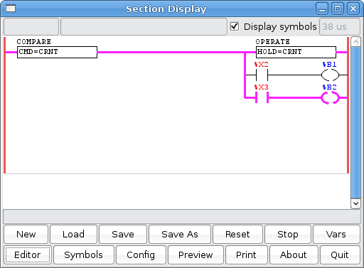
These two panels show the main ladder program the one on the left sends the signals (through HAL s32 pins ) to STEPGEN for forward and backward depending on which sequential step is active.
The %X bit inputs tell you when a step is active or not.The tool number is output to a word memory variable 'TOOL#' ( %W11 ). The %B10 switch is a momentary switch to start the index process.
The one on the right shows a counter to keep track of the current tool number. When the tool number = 4 the counter is reset to 0 again (so tool numbers are 0-3)

On the left is the subroutine. This checks to see if the commanded move is the same as the current position, if it is then sets the temporary holding register to the current position and finally lets the next step become active depending on what step was currently active.
On the right is the signed integers window, showing the current, commanded , hold register and the current tool number. The 'current' position is imported from STEPGEN through a s32 input pin. The 'commanded' is exported through a s32 out pin which is converted to a float signal and sent to STEPGEN. The 'hold register' and 'tool number' are held in temporary internal memory.
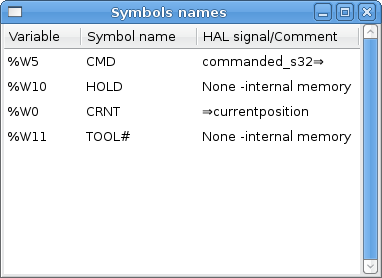
On the left shows how I filled out the SYMBOLS window to get named variables. It also shows the HAL signals connected to them.
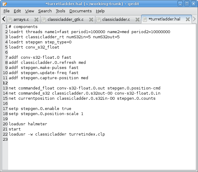
On The right shows the HAL file used to test this program which didn't use EMC . One thing to Note was that STEPGEN's commanded position information is on a FLOAT pin and Classicladder cannot write (or read) them, so it has to be converted first, using HAL's conv_s32_float component.
![[Home]](/chips.gif)