![[Home]](/chips.gif) Rastering With A Laser
Rastering With A LaserThere are many applications that need to run faster than usual. Especially laser rastering and high-resolution vector movements.
But there are several factors which slow down the system, like the time that LinuxCNC takes to execute each line of G-code.
Taking into account these difficulties, this guide aims to bring rastering to users in the least painful way possible.
Raster images are rectangular grids of pixels, or points of color, as it is typically used for the representation of photographic images. They are stored in image files with varying formats (BMP, JPG, PNG, etc).
Vector graphics is the use of geometrical primitives such as points, lines, curves, and shapes or polygons, which are all based on mathematical equations, to represent images.
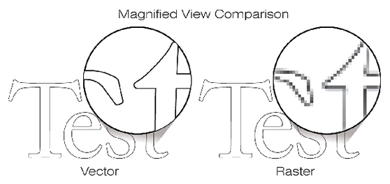
LinuxCNC is usually used to engrave vector graphics, moving a drill or a laser along the edges of a shape, for example. Rastering mode means move to the next pixel and update the laser power rapidly in one axis (like X axis). This movement should be at constant speed at X axis. You can find videos on YouTube about rastering to have a clearer idea.
Actually, if you go from X0 to X100 to X200 to X300, EMC2 will stop at X100, then go to X200 and stop, then go to X300 and stop. That means the laser will burn more time at the points 0, 100, 200, 300, etc. If you're engraving a picture, then the laser will stop at each pixel. So, the normal LinuxCNC configuration is impractical for this type of application, and it is necessary to make some changes to solve this problem.
From Hacklab Toronto, "Graster" is the name of a Image to Gcode converter (made in Ruby language), and it's designed to work with a particular kind of HAL component for LinuxCNC.
Graster produce two types of files: .NGC and .gmask files. NGC files contains the X and Y movements, and gmask files contains only the laser on/off commands. One reason to separate these instructions in two different files is that LinuxCNC interrupts the motion each time that normal Gcode on/off commands appears.
The laser is wired to spindle on/off (M3/M5) and is on if and only if the spindle is on and one or both of the Z axis (-0.002/+0.002) and digital out ("M62 P0"/"M63 P0") are on.
Controlling the laser with the Z axis can be tricky because LinuxCNC thinks that there is a moving physical object attached to the axis and tries to constrain its motion. The M62/M63 commands are realtime and instantaneous, meaning that they can be used to turn the laser on/off without affecting X/Y motion, at least in theory. You can put these commands on the same line as a motion command, in which case the laser will be turned on/off at the *beginning* of the motion.
The HAL component streams the laser on/off and moves the X axis at constant speed.
Graster installation:
If you want to use Graster to generate the Gcode and commands, you need to meet the following requirements:
HAL scripts and INI files installation:
Files required:
Look at the references [2] to get these files.
HAL scripts and INI files configuration:
This is the "hard" part. The HAL script and the INI file were purpose-built for the laser machine at Hacklab. Some work is required to adapt it to other hardware. The position of the laser is controlled by the X and Y axes, and the height of the table is the W axis. Finally, Z axis is used to on/off the laser.
So, you need to modify the machine parameters (like max speed, acceleration, step duration, etc) for your X,Y,Z axis (X,Y,W axis in these files). You also need to rewrite the pinouts of the parallel port.
If you run LinuxCNC, and an error appears with a message about the buffer size, try increasing the buffer size in the emc.nml file.
Run graster.rb for usage instructions. (in a terminal, run "./graster.rb")
The image can be any common format. PNG is probably best. A job can be configured with command line options or a configuration file. You can generate a default config file with the -g option. A config file looks like this:
 dpi: [500, 500]
 on_range: [0.0, 0.5]
 overshoot: 0.5
 offset: [1.0, 1.0]
 repeat: [1, 1]
 tile_size: [3, 1]
 tile_spacing: [0.125, 0.125]
 feed: 120
 cut_feed: 20
 corner_radius: 0.125
Graster output consists of a cut G-code file (filename.cut.ngc), a raster G-code file (filename.raster.ngc) and a mask file (filename.raster.gmask).
PNG image and its converted files, to get an idea of what graster does when it works:
These files can also be useful if you don't want to install graster but want to try it (if you already have configured the HAL and INI files for your machine).
I slumped over my keyboard, frustrated and defeated. After an untold number of attempts, I finally came to the solution to get rastering working. Some Googling showed me lists of pages talking about adding modules to blacklists, downloading the latest packages and building them, and compiling kernels, etc. Sometimes Linux is a pain. But thanks to the help and patience of Hacklab and the LinuxCNC community, this guide was completed.
[1] [LaserManual From Hacklab Toronto] (a bit outdated but may be helpful, especially the troubleshooting section)
[2] [LinuxCNC configuration and scripts for the hacklab.to laser]